Thursday, May 16, 2013

Critical structural elements for a manufactured home installation

Note that the constructions in this document conform to the Ohio Manufactured Home Commission’s rules (ORC 4781). Since these rules were developed from the HUD model guidance documents (24CFR-3285), the installations should meet other states’ manufactured home installation rules developed from the 24CFR-3285; but you should verify that fact. These constructions should also meet FHA guidelines since precursor documents to 24CFR-3285 were used to develop HUD 7487-Permanent Foundations Guide for Manufactured Housing, although some engineers may still require fully mortared piers, using strict interpretation of HUD-7487.

Directions for Typical Carriage and Marriage Wall Pier Construction

Photo 1

NOTE: Cap Blocks need to be 8” X 16” ASTM C145 concrete or 2” minimum thickness hardwood blocks on ALL piers. Other materials may be permitted EXCEPT 2” thick concrete blocks, which are NOT allowed as cap blocks or plates because they crack easily. An inspector may allow 2” blocks to be used lower in the pier stack; but be sure to check first with your inspector. Fully mortared piers should not require cap blocks.

ALSO NOTE: ALL piers are installed at a right angle to the carriage beams and marriage wall and need to be centered under the carriage beams or marriage wall. Pier blocks need to be within ½” of plumb. Piers at the ends of each carriage beam need to be within 24 inches of the end of the beams.

Rechecking the level of the home and tightness of the piers after shimming all piers the first time is highly recommended. Leveling the home in one area may throw off the level in another. The level of newly set homes and tightness of its piers should also be checked after about six months and a year because the slab or footings could have settled. A recheck should also be done if the home develops cracks in the drywall, doors or windows that do not open or close as before, or gaps in places where they were not present before.

Directions for Double Stack Carriage Beam Piers And Tie-Down Straps

Photo 2
Photo 3
Photo 4

*Some locations permit use of ABS pads. I do not support use of them without proper soil testing or strict installation according to the
manufacturer’s instructions, both of which are rarely done. So, in general, I don’t support their use. This is my document; so it follows my rules.

Directions for lateral brace installation

Photo 7   Photo 5 Photo 6

NOTES:

These photos show only one manufacturer’s lateral brace. Other manufacturers have slight variations.
Be sure to read and follow the manufacturer’s instructions for the particular brace being used.
The brace should not be bent or cut unless listed in the instructions.
No other beam clamp should be used or even manufactured for use with a particular manufacturer’s brace.
Yes, I have seen all of these cases.
Most lateral brace manufacturers require tie down straps at the corners of single-wide homes.
At least two braces are required for each home—located near opposite corners of the home and installed in opposing directions.
Homes over 76’ box length may need more braces.
Be sure to check the brace manufacturer’s installation instructions.

A PDF version of this document may be obtained by contacting:
Criterium-Cincinnati Engineers
criterium-cincinnati@fuse.net
513-474-9600

Tuesday, May 10, 2011

OMHC Approval of ABS (Pier) Pads

On April 20, 2011, the Ohio Manufactured Homes Commission (OMHC) held a hearing on proposed changes to Ohio Rule 4781, which governs installation of manufactured homes in Ohio. One change to those rules was to allow ABS pads as footings for manufactured homes. The exact wording is as follows:

"ABS footing pads shall be permitted if used in accordance with the manufacturer installation instructions and/or specification sheet of the specific ABS pad being used. The use of ABS pads must be used in conjunction with solid perimeter skirting in accordance with paragraphs (D) (1) to (D) (4) and (E)(1) to (E)(6) of rule 4781-6-02.5 of the Administrative Code."

We attended this hearing specifically to voice concerns about this revision to the previous rules that did not allow these pads. Three ABS pad manufacturers, Oliver, Polyvulc, and Tie-Down Engineering, also spoke at the hearing in favor of the changed rules. Our assessment of the attitude of the OMHC during the hearing was that it favored the rule change. Therefore, we wrote the letter attached to this blog post and submitted it to the OMHC within the comment period (less than 24 hours). That letter is included here:

OMHC Has Approved ABS Pads For Manufactured Homes


We found later that the OMHC had indeed passed the rule change, allowing ABS pads.
As the letter states, we are concerned that ABS pads will be used in conditions where they are not intended. Although the rule change states that the installer must follow the manufacturer's installation instructions, we had reviewed the instructions of the three main pad manufacturers and found them greatly lacking in detail, and where there is a lack of detail, there is opportunity for misuse. In a conversation with two of the manufacturer's representatives after the hearing, we were informed that other states that have allowed ABS pads also have training sessions particularly for ABS pads. Our feeling is that if ABS pads are allowed, they need to have such required training additional to following the manufacturer's instructions.

Essentially, our concern is that ABS pads require that soil be used as a replacement for concrete footings or slab. Granted, some soils can be "hard as concrete" when at certain moisture content and without organic matter and voids. That is to say, the soil has the same bearing capacity as concrete. However, unlike concrete, which has a bearing capacity that changes little over a wide range of conditions, the bearing capacity of soil can change dramatically.

Therefore, if soil is going to be used to replace concrete, the soil conditions must be controlled. In the one decently documented case where ABS pads were successfully used, soil moisture and frost heave were well-controlled. In this case, insulated skirting to maintain temperatures above freezing in the crawlspace and drainage around the home's perimeter were used. The manufacturers' installation instructions usually state a minimum required soil bearing capacity and that the pads be placed "at or below the frost-line". The insulated skirting, moves the frost line to grade. The required soil bearing capacity is in part essentially a requirement for proper drainage because the soil bearing capacity can drop significantly as the soil moisture increases. Thus, soil moisture needs to be controlled through proper drainage.

But, can installers be trusted to measure soil bearing capacity accurately or to accurately calculate whether an ABS pad be able to take the weight put on it? Can most inspectors be trusted to check the right parameters and review the required information. The OMHC has left those questions wide open. Currently, installers and inspectors are not required to have special training. Therefore, no two installers will be doing the same installation or checking the same parameters. That is why we wrote the letter to the OMHC. If ABS pads are going to be used, they need to be used properly and uniformly. They cannot simply be used in place of concrete footings because soil is not exactly the same as concrete and the weight being put on the soil will usually be more for ABS pads than for concrete footings.

We are going to continue pursuing the issues of proper training for ABS pad use. We are also aiming for the requirement that a licensed engineer approve the use of ABS pads to assure that homeowners get the home that they believe they are buying. In a future blog, we plan on commenting research sponsored by the Ohio Manufactured Home Association which has been used to back the approval of the pads. Stay tuned.

Friday, March 11, 2011

Shingle Overlays--Just Say No Way

Eventually, each owner will need to replace the shingles on his/her residence. At that time, the owner will need to decide whether to install new shingles over the existing shingles, known as overlaying, or to strip all of the shingles off to the roof deck before installing the new shingles. For the former, the existing flashings are also normally kept or supplemented. For the latter, flashings are normally replaced, as well as the underlayment. I will state up front that my firm, Criterium-Cincinnati Engineers, does not support overlaying and this blog lays out our reasons.

Building owners usually only give one reason FOR overlaying shingles and that is the cost is less than fully replacing the existing roof components. On the other hand, roofing professionals and engineers have a number of reasons NOT to overlay. These reasons include the following:

  • Total removal of all of the old roof materials allows inspection of the roof deck, valleys, joints between the roof and walls or chimneys, and areas around roof penetrations, such as sanitary or roof vents. This inspection could discover rotted wood, insects, holes and a number of other issues that could compromise the roof. Some might argue that these issues are visible from within the attic. Having been in more than a few attics, I can assure that these issues are not always visible. For some residences, the attic cannot even be entered and in others no attic exists, such as in residences with cathedral ceilings. We believe that a residence's first roof replacement should particularly not be an overlayment because of the poor quality of some builders.
  • Total removal of the old shingles can assure that an underlayment is installed. Underlayments perform two main functions: an additional water barrier against leaks in the shingles and separation membrane between the shingles and the roof deck. Shingles installed directly on the roof deck sometimes melt or stick to the deck. But, shingles expand and contract on the roof deck as they heat up and cool down. Shingles stuck to the deck are restricted in their movement, which could result in the shingles buckling or tearing, shortening their life or creating leaks.
  • One of the most vulnerable parts of the roofing system is valleys. Valley flashings can fail and more than a few of these flashings have also been installed incorrectly. Poorer quality builders may not have installed valley flashings at all, trusting that the underlayment will protect the valley. Instead, shingles are weaved across the valley. (By the way, Criterium-Cincinnati Engineers does not support weaving shingles over valleys because of the increased chance for leaks.) Replacement, rather than reuse, of the valley flashings helps assure that valleys will be adequately protected. If the roof is older, new techniques have been implemented since the old roof was installed that adds better protection. One such technique used by better quality roofers is to install an elastomeric membrane beneath the flashing. Not only does the membrane protect against rain leaks, it protects against leaks due to ice dams.
  • In some areas of the country, roof areas above eaves are another area that may need extra protection because they are where ice dams tend to develop. These areas are also vulnerable to shingle lifting due to wind. Better quality roofers install an elastomeric membrane as underlayment over this area in addition to the underlayment used on the rest of the roof. Most original roofs do not have this degree of protection.
  • Rakes, the roof area over the gable, are other areas that are exposed to potential lifting. During overlayments, another layer of shingles are laid along the rake, which raises the edge of the shingles where they are better exposed to the wind and lifting.
  • Roof penetrations, such as vent pipes, also need to be flashed to prevent water leaking through the gap between the roof deck and penetrating object. But, these flashings can also fail and are sometimes damaged by high winds. When a roof is overlaid, these flashings are usually not replaced. So, what happens if these flashings fails before the second (or third) roof is replaced? Removal of the flashing could damage the roof shingles. The usual patch is to smear the flashing seams with tar or roof caulk. Tar or caulk does not normally last as long as the roof shingles and will have to be periodically inspected and repaired. If a leak develops in the tar or caulk, the usual (wrong) solution is to apply more tar or caulk, and the new material commonly fails quicker than the previous material. Even if the flashing is replaced, the best place for it is in the first layer of shingles, which is virtually impossible when more than one layer of shingles is installed.
  • Many two-story homes have second-story exterior walls that meet first story roofs. Flashing is supposed to be installed between the wall and the roof to prevent water entering through the gap between the roof deck and wall sheathing. As other internet posters on the subject of overlayments point out, roofers installing overlayments try to reuse the installed flashing by bending and weaving it with the new shingles. Alternatively, they may also pry out the siding, shove new flashing up under the siding and weave that flashing with the new shingles, leaving the old flashing in place. We have also seen where a roofer installed a continuous flashing up under the siding and ran a bead of roofing caulk between that flashing and the new shingles. And we have also seen where new flashing was not installed at all, but the roofer relied on roofing tar to stick the edge of the new shingles to the old ones. None of these alternatives are acceptable, especially if the old flashing leaks.
  • The addition of a new layer of shingles adds considerable weight to the roof structure. A new layer of shingles weighs about 2 pounds per square foot. Although that amount of weight does not seem like a lot, think in terms of 200 pounds for ONE layer of shingles for a 10 foot X 10 foot area (one square). Add the weight of the original layer of shingles and the total weight of the shingles is now at least 400 pounds per square. Over time, this weight can cause rafters to bow or the roof to sag, particularly for roofs with long rafter spans (distances between supports), rafters that lack ties between opposing rafters, or homes with balloon framing. Likewise, some builders use the maximum spacing between rafters with the minimum thickness of roof sheathing allowed by codes. The result is that the deck sags between the rafters causing the waviness sometimes seen in some roofs. If the roof has developed sags between rafters with only one layer of shingles, what do you think the roof will do with two or more layers? Add an abnormal snow load and the roof could collapse, as some folks found out during the 2010-11 winter.
  • As stated, shingles expand and contract as they heat and cool. The degree of shingle expansion and contraction with change in temperature further varies with thickness, material composition, manufacturing method, lot and a number of other factors. If one layer of shingles is expanding and contracting differently than the second layer of shingles, shear stresses can set up in the layer that expands or contracts less, which eventually will cause tears in the shingle. If these tears are exposed to weathering, the shingles life can be shortened. We have observed that many builders install thinner, cheaper shingles as the original roof on many homes. Homeowners, on the other hand, tend to install thicker sculptured shingles as the overlayment because homeowners believe they will get longer life from them. Guess what that usually means? Yep, two different types of shingles with likely different expansion and contraction properties that are also were likely not even made by the same manufacturer. Since the lower layer of shingles are thinner, they can expand and contract more than the overlayment shingles, which results in tears in the overlayment shingles.
  • Multiple layers of shingles add insulation to the roof, which leads to a hotter attic. In turn, a hotter attic leads to the shingles getting hotter. Heat is a major factor in breaking down shingle materials. Further, a hotter attic means greater expansion and movement of the shingles. The result is a shorter shingle life. A hotter attic also means that a homeowner could be paying more for cooling in the summer when the attic heat is transferred into the living space.
  • We have noted many cases of vertical stacking installation of the shingles. Vertical stacking is where the shingles are installed in eave to peak columns rather than installing them diagonally starting at one of the corners over and eave. Although shingles on properly installed roofs can start curling over time, particularly in overly hot attics, the shingles along the sides of the columns of vertically stacked shingles begin to curl more often and quicker than other shingles. The curled shingles make an uneven base for the new shingles, which creates uneven pressure on the new shingles. In turn, the uneven surface can cause tears in the new shingles exposing the inner part of the shingles to weathering, leading to shortened life.
  • Overlayment shingles are very often not aligned horizontally with lower layers. This misalignment results in the mid-area of upper shingles arching over the tab ends of lower shingles—again with the uneven base thing, causing the tears, weathering, etc.
  • Many shingle manufacturers offer a guarantee. However, that guarantee may not apply to overlays.
  • Dark streaking on roofs is usually caused by a very, very hardy blue-green algae. What happens when these shingles are overlaid with new shingles? That question has not been answered; but, the possibility exists for the algae to spread from the old shingles to the new ones.
  • Shingles that are failing begin to hold moisture. One sign of excess moisture is moss growing on the roof. When new shingles are laid over shingles that are holding moisture, that moisture has to go somewhere. If a moisture barrier exists below the roof deck, such as closed cell foam and insulation with a vapor barrier, the moisture could become trapped between the moisture barrier and the shingles, potentially creating a wood rot condition. Speaking of the moss, how sure are you that the roofer has bully removed the moss before installing new shingles? Exactly what happens to the organic matter trapped under the new shingles? Organic matter is also going to be in the old shingles from the moss rhizoids (root-like structures) that have grown into and between the shingles.
Most roofers estimate that useful life of overlayment shingles can be as much as 25% less than their claimed life, which means that overlayment may not cost less in the long run. For sure, if the roof leaks, the cost of repairing the roof and damaged interior finishes could also vaporize any cost savings from overlayment. The bottom line is shingles overlays just might not be worth the expected savings.

Sunday, January 30, 2011

General Guidance and Anchoring System Options for Manufactured and Modular Home with Perimeter Support Foundations (REV.)

Overview:

This document discusses the proper methods (and more than one exists) for anchoring manufactured and modular homes with perimeter support foundations, which will be better defined just a little further on. The subject of this document is primarily proper anchoring methods because I frequently find mistakes in these anchoring systems. In my internet searches, I have not come across other publications that specifically address this topic. Building codes and other regulations, such as the Housing and Urban Development's model regulations, and manufacturer installation instructions describe or dictate construction of other foundation elements and the installation of the home; but details on anchoring requirements for these foundation systems is sketchy.

Therefore, I wrote this document to summarize the anchoring methods, and errors in anchoring methods, that I have found while performing over 500 FHA or other inspections on these homes (and all of the photos in this document came from those inspections). This document covers both manufactured and modular homes because some of the home constructions have very similar foundation and anchoring systems. Although Criterium-Cincinnati Engineers does not get many calls for modular home inspections, those I have inspected leads me to believe that the prevalence in anchoring issues are similar to those for manufactured homes.
Note that this article and its contents are only intended as guidance. It is not intended to be used as a design document or to replace any building codes or other applicable rules. Be sure to check local and state building code or other state installation rules for specific installation requirements.


General Guidance for Manufactured and Modular Home Foundation Systems:

Manufactured and modular homes mainly differ visually in that manufactured homes arrive on-site on their own wheels while modular homes are transported on-site via another carrier, such as a flat-bed trailer. For a more detailed description of differences, refer to these web sites:

The majority of the manufactured and modular homes have pier (rather than perimeter) foundation systems. Photo 1 shows a typical pier system.


Photo 1. Typical manufactured home pier system.

This foundation system uses piers, commonly constructed from concrete blocks (seen in the photo above) for the foundation system. The piers are supposed to be erected on either poured concrete footings or slabs For manufactured and on-frame modular homes that have I-beam structural members that are part of the home structure, the piers are located under and support the I-beams. (For manufactured homes, these beams are commonly called carriage beams because they are used to transport the home to the site. To use common terminology for both manufactured and modular homes, I use "home structural beams" in this document.)
Vinyl skirting or a concrete block perimeter wall is usually installed around underside of the perimeter of the home to enclose the pier foundation system. This skirting or perimeter wall is not part of the foundation system and is not structural. Skirting and perimeter walls have purpose, though, in that they help keep water and vermin from getting under the home, help protect the plumbing from freezing and prevent wind (more particularly high winds) from getting under and lifting the home.

Manufactured homes come in both single and doublewide constructions, while modular homes are usually doublewide construction. Singlewide means that the home is a complete home, constructed so that it can be moved into place as a unit and set on the foundation system. Doublewide structures arrive on-site in two halves that are moved together on a foundation system and the halves are then screwed together. Each half of the doublewide home comes with a hinged roof. Once the two halves of a doublewide are assembled, the roof is rotated into position and assembled. Although not yet common, complex manufactured and modular homes, such as multiple story structures, are being built. Foundation systems for the more complex structures are similar to the single-story structures, although adjusted for the extra weight.

Both single and double-wide homes would have piers under the home structural beams, while a double-wide home would also have additional piers supporting points along the home's marriage line, as specified by the manufacturer. (The marriage line, which is sometimes also known as the mating line, is where the two halves of a double-wide home meet.) The anchoring systems for pier foundations for manufactured and on-frame modular homes is either a lateral brace system or steel straps with concrete or ground anchors, which are shown in Photos 2 and 3, respectively.

Photo 2. An example of one manufacturer's lateral brace anchored to a concrete slab.

This article, though, is about anchoring manufactured and modular homes that have perimeter foundation systems. The terminology "perimeter foundation system" might inspire a mind picture of the typical site-built home foundation system where the perimeter of the home is supported directly on the foundation system. Some manufactured and modular home foundation systems are similar to site-built home foundation systems, and they are discussed later in this article. However, most manufactured and on-frame modular homes with perimeter foundation systems are supported on H or I-beams that are in turn supported on the perimeter foundation system. In this article, these beams are called foundation beams (and can be seen in the photo below). Homes with foundation beams have different anchoring requirements than homes without foundation beams, and the former are discussed first. A typical foundation beam installation is shown in the Photo 4.

Photo 3. An example of one manufacturer's steel strap anchored to a concrete slab.

As the photos throughout this article show, perimeter foundation systems can be used for either basement or crawlspace foundations. Normally, though, foundation systems with center-support steel columns are used in homes with basements to allow for possible finishing of the basement. Basements and crawlspaces could have either gravel or concrete slab floors; but all should have footings installed under the center support columns or piers.

Manufactured and modular home perimeter foundations are constructed from either poured concrete or concrete block, similar to site-built homes. Local building codes usually dictate how foundations should be constructed. If the area has no local building codes, construction usually has to adhere to state building codes, which are usually a derivation of the International Building Codes (although the state's current building codes might not be as current as the International Building Codes). Homes installed in areas under the jurisdiction of a building department usually need to have a building department permit and at least a foundation system inspection. Further, installation permitting and inspection requirements can vary from state to state and even from area to area. Be sure to check local building code requirements specific to manufactured and modular homes. Concrete foundations usually have pockets built in the walls to support the ends of the foundation beams similar to the pockets installed in site-built home foundations to support the ends of these homes' main beams. Concrete block foundations usually have pilasters installed to support the beam ends, and the concrete blocks that comprise the pilasters need to have their holes completely filled with concrete. The concrete fill needs to have rebar reinforcement installed in the concrete. That being said, some concrete block foundations have pockets for the foundation beams instead of pilasters and some poured concrete foundations have pilasters for the foundation beams instead of pockets. Still, even if pockets are installed in a concrete block foundation, pilasters are still usually built in the foundation under the pockets and the blocks are filled with concrete with rebar reinforcement. Examples of foundation beam installations are shown in Photos 5 through 7.

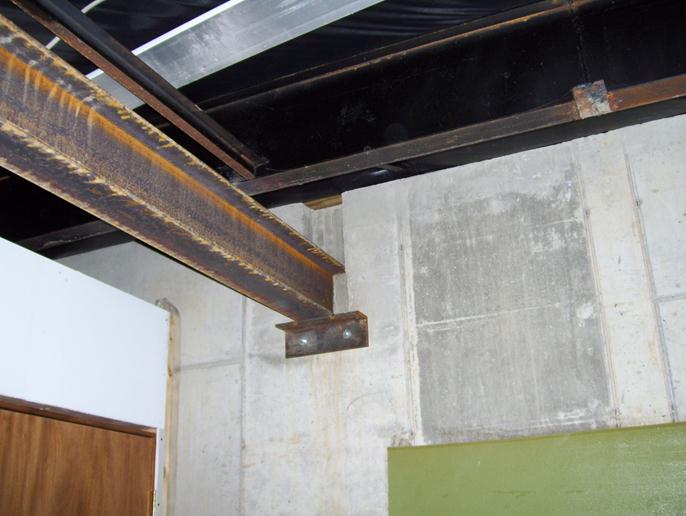
Photo 4. An example of a manufactured home with a perimeter foundation system that uses foundation beams and concrete block center piers.

The ends of all structural beams for manufactured and on-frame modular homes need to be supported. In Photo 8, pilasters built next to the end foundation wall are used to support the structural beams. Other acceptable means for supporting the ends of the structural beams that I have found were pilasters built into the foundation walls, steel columns or foundation beams. Unlike the pilasters supporting the structural beams, concrete block columns do not have to be fully mortared, but must have proper cap blocks, which are usually half-filled 8-inch or 4-inch thick concrete blocks or 2-inch minimum hardwood boards that are at least the same dimensions as the pier blocks. Piers and steel columns need to have proper footings. If foundation beams, piers or steel columns are used instead of pilasters to support the ends of the home structural beams, they need to be located within 2 feet of the ends of the home structural beams.

Photo 5. Example of a foundation beam installed in a pocket on top of a pilaster in a concrete block foundation wall.

Photo 6. Example of a foundation beam installed on a pilaster of a concrete block foundation without a pocket.

Photo 7. Example of a foundation beam installed in a pocket in a poured concrete foundation wall.

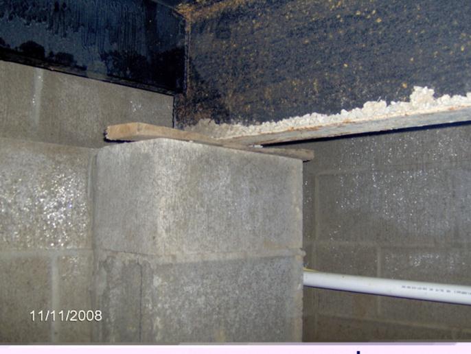
Photo 8. An example of piers supporting a manufactured home's structural beams.


Photo 9. An example of shimming for the end of a home structural beam.

As Photo 9 shows, the ends of the structural beams may need shimming. While the home's structural beams are shimmed, the foundation beams are not normally shimmed. When wood shims are used, they need to be a minimum 4-inch wide hardwood and used in pairs, as shown in the photo. Shims are not usually used between the foundation or pilasters and the foundation beams. The reason is that the home is usually leveled by installing shims between the foundation beams and the home structural beams because adjustment needed between one foundation beam/structural beam contact point and another can vary significantly. Shims are also sometimes used between the middle support piers and the foundation beams. The proper shims between the home structural and foundation beams will be discussed in more detail later in this article. But the shims between the middle support piers and the foundation beams are a minimum 4-inch wide hardwood and used in pairs

As Photos 4 and 10 show, the foundation beams are located in nearly the same locations as would be the piers for a pier foundation home. That is, steel beams run the width of the home in similar locations to the piers and support the home's structural beams and marriage line (if needed) in the same way as the piers. The ends of the foundation beams are supported on the home's front and rear perimeter walls.

Photo 10. An example of a perimeter foundation system that uses foundation beams and center support columns.
 
Double-wide homes usually have either concrete block piers or steel columns supporting the center of the foundation beams. Photo 10 shows an example of steel columns while Photo 11 shows an example of concrete block piers. Columns need to be fastened at the bottom to the footing or slab and at the top to the foundation beam or other marriage line structure, which will be discussed later. These fastening requirements hold true for other locations steel piers might be used, such as at the ends of the home structural beams.
Depending on the manufacturer requirements, extra piers may be needed to support the marriage line at other locations other than above the foundation beams, as shown in the Photo 11. Installation instructions usually show where marriage line piers are needed. For newer homes, most manufacturers indicate where support is needed along the marriage line with some kind of mark on the bottom board (the membrane covering the underside of the home). If the manufacturer calls for support of the marriage line at a point less than 2 feet from a foundation beam, then additional support may not be needed.

I have been asked whether piers have to be unmortared (a.k.a. dry-stacked) or mortared. Mortaring is required in Housing and Urban Development (HUD) 7487. Permanent Foundations Guide for Manufactured Housing, the guidelines used for foundation inspections for Federal Housing Authority (FHA) loan approval. The latest HUD standard (24 CFR 3285. Model Manufactured Home Installation Standards) used as a model for current manufactured home installations does not require mortaring of any foundation pier blocks, including the marriage line piers, unless they are specially designed or in flood plains. This standard does require piers from 32 to 60 inches to be double-stacked, as shown in Photo 11, and piers over 60 inches to be designed by a licensed engineer or architect. Additionally, the standard requires that ALL piers for homes in flood plains be designed by a licensed engineer or architect and meet the requirements of the local flood plain authority. But, the standard provides no information for the piers used in perimeter foundation systems other than they are designed by a licensed engineer or architect or adhere to the manufacturer's installation instructions. I have found both mortared and unmortared marriage line and end support piers. I have also not found any issues with properly installed unmortared piers built on properly designed and installed footings.
Homes that have steel columns instead of piers may also need to have support for the marriage line that is farther than 2 feet from the foundation beams. In these cases, additional steel columns can be installed, or if a wall has been installed under the marriage line, for example as part of finishing a basement, the wall can be extended to the marriage line to provide support. However, that wall then becomes a load-bearing wall. Other methods can also be used to support the marriage line between foundation beams; but a licensed engineer or architect should be hired to specify such construction.

Double-wide homes also have blocking installed on top of the foundation beams above all center piers to support the marriage line. Foundation systems that use steel columns instead of piers to support the foundation beams also have blocking is installed on top of the foundation beams above the columns, as shown in Photo 12. Blocking is usually wood, although concrete blocks can also be used as long as a cap block is installed on top of the blocks, as visible in Photo 11. Blocking needs to be at least the width of the foundation beam flange and at least twice as long as wide to assure stability.

Gaps between the top of piers and blocking along the marriage line need to be shimmed. Shims need to be at least 4 inches wide, hardwood or equivalent and used in pairs. These shims need to be driven tight between the pier or blocking and the marriage line.

For information on the currently acceptable construction piers, please refer to 24 CFR 3285: MODEL MANUFACTURED HOME INSTALLATION STANDARD (http://www.access.gpo.gov/nara/cfr/waisidx_08/24cfr3285_08.html) or your state's current installation standards (which should be a derivation of 24 CFR 3285). Keep in mind that these standards defer to the manufacturer's installation instructions, if available. Installers should read and follow the manufacturer's installation instructions. Not following the manufacturer's instructions could void the home's warranty or the expose the installer or others to liability issues. The information presented in this article is not intended to replace the installation instructions.


Photo 11. Examples of concrete block piers under the marriage line and mid-point of the foundation beam.

Photo 12. Examples of marriage line support blocking and a steel column support under the mid-point of a foundation beam.

Anchoring Systems for Perimeter Foundation Systems:

To properly anchor manufactured and on-frame modular homes with perimeter foundations, the foundation beams need to be anchored to the foundation AND the home structural beams need to be fastened to the foundation beams supporting them. This latter part of the anchoring system seems to be most often forgotten or unknown. No one method exists for anchoring the foundation beams to the foundation; but the anchoring method needs to meet these basic criteria:
  • BOTH ends of all foundation beams need to be anchored to the foundation.
  • If the foundation beam ends are not located in pockets that are tight enough to prevent twisting or sideways movement of the beams, both sides of each end of the foundation beams need to be anchored or the full widths of the beams have to be anchored (as shown in the example photos later in this article).
  • The anchors have to prevent the foundation beams from being pulled laterally out of the pockets or off the pilasters, as could happen if the foundation wall moves outward.
  • The anchors have to prevent the foundation beams from being pushed sideways off of the pilasters.
  • The anchors or the foundation pockets have to prevent the ends of the foundation beams from being lifted vertically off of the pilasters or within the pockets.
Manufactured and on-frame modular homes installed on poured concrete foundations have more anchoring options than concrete block foundations because anchors for the latter need to be tied to the reinforcement in the concrete-filled blocks in the foundation. Photos in this section show examples of a variety of anchoring methods that I have found during inspections of manufactured homes with foundation beams.
Photo 13 shows the end of a foundation beam on top of a pilaster. By far the most common method for anchoring foundation beams to concrete block foundations is using the rebar installed to reinforce the pilaster. As shown, the rebar is extended above the pilaster, and bent over onto and welded to the foundation beam, as shown in the photo. This photo shows the preferred method for attaching the rebar to the beam in that the rebar ends are kept short and at least 2 inches of the rebar is welded solidly to the beam (indicated by the arrow). A similar rebar anchor is on the other side of the beam to prevent the beam from moving sideways on the pilaster. Both sides of each rebar end should be welded to the beam.

Photo 14 shows another variation of a rebar anchor that is acceptable, although not as ideal as the previous photo. In this installation, a similar rebar anchor was installed on the other side of the beam. This anchor would be more ideal if the area around the base of the rebar inside the block were mortared to stiffen the rebar.

Photo 15 shows another rebar/beam anchor that is not acceptable. As this photo shows, the rebar is much longer than those shown in Photos 13 and 14. Although the longer rebar means that it can be bent into position more easily, the longer rebar does not restrain the beam from excessive movement. Furthermore, only the very end of the rebar is welded, which could allow the rebar to break loose if the beam moved. A closer pocket around the beam would restrict the beam from moving sideways; but the excessive length of the rebar would not prevent is from being pulled from the pocket. This anchor could be fixed by shortening the rebar on both sides of the beam and welding at least 2 inches of the rebar to the beam.

Photo 13. Example of pilaster rebar being used also as an anchor for a foundation beam.

Photo 14. Another example of pilaster rebar also being used to anchor a foundation beam.
:
Photo 15. Example of pilaster rebar being used improperly as an anchor for a foundation beam.

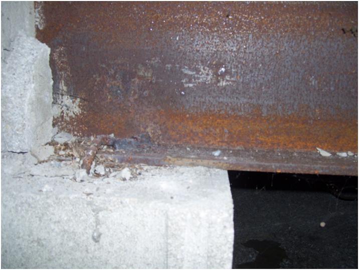
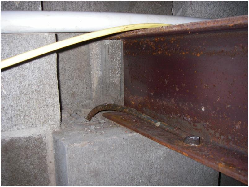
Improper welding of the rebar is a common issue with the rebar anchor, as shown in the Photo 15. If enough off the rebar is not welded to the foundation beam, the weld can break loose, as indicated by the arrow Photo 16. In this case, the installer apparently tack welded the rebar and the weld had later broken loose simply by the rebar pulling upward on the weld. If the weld could break loose simply due to the rebar force, imagine the rebar trying to prevent the beam from moving. As with the case shown in Photo 15, to fix this issue, the rebar should be shortened first and at least 2 inches of the rebar welded the beam.


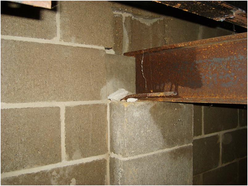
Photo 17 shows a gross misuse of a rebar anchor. As the photo below shows, the rebar is run from the foundation footing to the foundation beam. Obviously, this anchor would not constrain movement of the foundation beam and would therefore not be an acceptable anchor. This photo also shows another issue with the pilaster construction. Gaps in the mortar show that the blocks were not fully mortared, nor filled with concrete or reinforced with rebar.. At least, this installer used a sold 4-inch concrete block on top of the pilaster to properly transfer the beam load fully across the pilaster.

Photo 16. Another example of an improper rebar anchor; but in this case, the rebar has pulled loose due to not being welded properly.

Photo 17. Another example of an improper rebar anchor for a foundation beam. Also shown is an example of an improperly constructed pilaster.

As stated previously, poured concrete foundations offer additional anchoring options as shown in the following Photos 18 and 19.

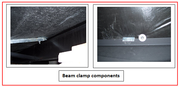
Photo 18. Example of a proper foundation beam anchor using angle iron that has been bolted to foundation and welded to the foundation beam.

Photos 18 and 19 show two variations of the same type of anchor, except one was installed under the foundation beam and the other over the foundation beam. Both photos show that the anchor is bolted solidly to the foundation and both are wider than the beam flanges. The foundation beams need to be welded fully to the anchors, as can be seen clearly in Photo 19. Even if the anchor is installed above the beam, welding is needed to prevent the beam from being pulled upward or out of the pocket. Note also that the beam pockets in both photos are just wide enough to accommodate the beam, which helps prevent beam twist. However, these types of anchors should also help prevent twist.

Photo 20 shows a clever use of tie-down straps normally used to anchor homes on pier foundation systems. In this case, the straps normally used to fasten piered home's structural beams to a concrete footing or pad have been used to anchor this home's structural beams the concrete foundation. Further, the strap has been properly looped around the carriage beam according to the manufacturer's instructions, which firmly secures the strap buckle to the home structural beam. Many installers do not properly install these straps. The additional strap between the carriage beam and the end foundation wall should not be needed because the home structural beam's movement is constrained by the foundation and other anchors; but the manufacturer's installation instructions should be followed to prevent voiding warranties. Nonetheless, this installation does not meet the overall guidelines stated earlier because the foundation beams have not been anchored to the foundation or the structural beams have not been fastened to the foundation beams. Note also that this photo shows an example of an installation with a foundation beam installed near the end of the home structural beams instead of a pilaster, pier or column.

Photo 19. Example of another proper anchoring method using angle iron bolted to foundation.


Photo 20. Example of an anchor method using steel strap anchors attached to the foundation.

In some cases, concrete block is sometimes installed on top of a poured concrete foundation. This kind of change can happen if additional headroom in a basement was desired after the concrete foundation has already been poured. Photo 21 shows the way one installer, almost acceptably resolved this issue. The installer built pockets in the block to constrain the foundation beams and then welded angle anchors to the beams that extended to the poured concrete foundation. However, the installer did not bolt the angles to the foundation, making this installation not acceptable. The installer also did reinforce the concrete blocks surrounding the foundation beams by installing rebar that was anchored into the concrete foundation and filling the block holes with concrete. In fact, I believe that the designer should have specified that all of the concrete block sections be reinforced and concreted.


Photo 21. Example of a possible proper foundation beam anchor used on a mixed materials foundation. However, the angle section needs to be bolted to the foundation.

To complete a proper anchoring system for foundation beam systems, the home structural beams need to be fastened to the foundation beams. Manufacturer installation instructions that I have reviewed require that the structural beams be fastened to the foundation beams at ALL points where they cross. Manufacturers usually allow two fastening methods, either 1/4"-inch fillet welds or bolting. An example of welding is shown in Photo 22 and bolting in Photo 23.

Photo 22. Example of a proper welding between a structural beam and foundation beam.

Photo 23. Example of a bolt fastening a structural beam to a foundation beam.

By far, welding is usually more expedient than bolting and more secure. Installers considering bolting should check with the manufacturer to assure that drilling holes in the home structural beams will not void the home's warranty. If bolting is allowed, installers should also check for the manufacturer's specifications for bolt size and torque. Installers should also verify whether washers and lock nuts are needed. Installation instructions for welding usually require that both sides of either the home structural or foundation beam be welded; but installers should follow the manufacturer's specific instructions for the home. Installation instructions also normally require that each joint be fully welded across the full width of the structural or foundation beam, as shown in Photo 22. A number of installers us a weld of only 1 or 2 inches, which is normally not acceptable. Alternative methods of fastening the two beams together may exist; but the installer should check with the manufacturer for acceptability. In the absence of installation instructions, installers should follow local building codes requirements for fastening the beams together.

Earlier in this article, I noted that shims are normally installed between the foundation beams and home structural beams rather than between the foundation beams and the foundation. Wood shims, as shown in Photo 24, are not acceptable because they may not support the load and they do not allow proper fastening of the foundation beams to the home structural beams. Additionally, when joints with shims are welded, the shim needs to be fully included in the weld, as shown in Photo 25.

Photo 24. Improper use of wood shims between a foundation beam and structural beam.

Photo 25. Proper welding of the metal shims used between a structural beam and foundation beam.

Alternative Foundation Systems and Anchoring Methods:

Previously, I mentioned a second general type of manufactured and modular home construction that is supported directly on the perimeter foundations without need for foundation. From the underside, these homes look very similar to site-built homes, as can be seen in the Photos 26 through 28. The first two photos are manufactured homes and the last photo is a modular home. The marriage line of these homes are usually supported on steel columns or concrete block piers. A load-bearing wall could also be used instead of columns; but, the homes I have inspected that had frame walls built under the marriage line also usually had steel columns. If a frame wall is planned to be used as a load-bearing wall instead of steel columns, consult the manufacturer's installation instructions or local building codes to verify that load-bearing wall construction is acceptable.

Note that in Photos 26 through 28 the marriage line is the equivalent of the main beam in a site-built home, except one-half of the marriage line "beam" belongs to each side of the home. The two halves are screwed together when the homes are mated together. These homes come in a variety of constructions, and manufacturers are likely to make changes in the future to make the homes look even more like site-built homes.

Another difference between these homes and those with foundation beams is that these homes are anchored around the perimeter to a sole plate that sits on top of the foundation. To fully anchor these homes, the sole plate must be anchored to the foundation AND the home needs to be anchored to the sole plate.

Photo 26. Example of one style of manufactured home that uses perimeter anchoring to a sole plate instead of foundation beams.

Photo 27. Another example one style of manufactured home that uses perimeter anchoring to a sole plate instead of foundation beams.


Photo 28. Example of one style of modular home that uses perimeter anchoring to a sole plate instead of foundation beams.

Two methods for anchoring the sole plate are shown in the following Photos 29 and 30. Photo 29 shows a sole plate anchored to the foundation using an anchor bolt while Photo 30 shows a sole plate attached to the foundation using metal straps fastened to the foundation. Some installers have also used concrete anchors and bolts to fasten the sole plate to the foundation. Local or state building codes, the International Building Code or the manufacturer instructions should be consulted to determine acceptable methods for how the sole plate is fastened to the foundation. Keep in mind that the weaker the fastening method, the more anchors might be needed. For example, I would expect fewer anchors being needed for the anchor bolt fasteners in Photo 29 than the strap anchors in Photo 30.


I have observed two variations in home construction that determine how the home is anchored to the sole plate. For homes with wood joists, the joists can be fastened to the sole plate directly, as shown in Photo 31. In this installation, the sole plate was oversized and lag screws were used to screw joists to the sole plate.
Homes with steel joists may have a sole plate attached to the bottom of the joists, as shown in the Photo 32. As can be seen in this photo, this sole plate is then screwed to the foundation sole plate.

Photo 29. Example of a sole plate bolted to the foundation. The home is then fastened to the sole plate.

Photo 30. Example of a strap anchor being used to anchor a sole plate to foundation.

Photo 31. Example of a home joist being screwed to the sole plate to complete the anchoring system.

Photo 32. Example of a manufactured home bolted to a sole plate.

Some homes have band joists that extend below the floor joists, which can be seen as oriented strand board in Photo 29. For these homes, the band joist can be fastened to the sole plate from the exterior side of the rim joist prior to siding being installed over the band joist. On the other hand, some manufacturers extend the exterior sheathing below the floor level and attach the joists to the sheathing, which appears to be the case in Photo 30. Manufacturers may have specified methods for anchoring the home in the installation instructions. If the instructions do not specify an anchoring method, refer to local or state building codes or contact the manufacturer or a licensed engineer or architect for recommendations.

Although manufacturers might allow anchoring the home using the rim joist or exterior sheathing, I do not favor this method of anchoring. One major issue with this anchoring method is that a gap is sometimes left between the exterior sheathing or band joist and the sole plate because of an error or inaccuracy in construction. This gap could be sizeable. For one home I inspected, a gap of nearly 1 inch was present in some places around the home's perimeter. The strength in this anchoring method comes mainly from the contact between the sheathing or band joist and the sole plate woods when the fastener pulls them together. If a gap is present, the fasteners take the entire load, which weakens the anchor. Additionally, verifying whether the home has been properly anchored is difficult to impossible once the siding has been installed. Due to the number of issues with this method of anchoring the home, I recommend that an alternate method that anchors the home's joists to the sole plate be used if possible.

The Wrap:

I have tried to be as thorough as possible in writing this article; however, I have likely missed some important points. Further, manufacturers periodically change designs that could change installation requirements. Further, so much variation exists currently in home designs that a particular home's foundation system and anchoring method may be different than presented in this article; but those in this article may still be acceptable.

Another important point is that recent HUD rules require states to develop installation rules based on the HUD model standards (24 CFR 3285). HUD further required that new manufactured home sets be inspected according to each state's rules. For installations not covered in the HUD or state rules, such as perimeter foundation systems, HUD rules and likely many state rules defer to the manufacturer's installation instructions or specifications by a licensed engineer or architect designs. If other state rules are similar to those in Ohio, this information must be obtained prior to obtaining a permit to begin construction. Make sure you are aware of your state's requirements so that a potentially stiff fine or reconstruction costs are avoided.

Please be sure to contact us with questions or comments or to request a PDF version of this article. I hope to revise this article based on those comments and questions.

Sunday, January 23, 2011

OMHC clarifation of homeowner involvement in manufactured home installations

In Ohio, owners can do all or part of their manufactured home's of the installation.  Further, only Ohio Manufactured Homes Commission (OMHC) licensed installers can do those parts of the installation for which an installer is hired.  Until now, the OMHC had not fully clarified the homeowner qualifications or responsibilities should they choose to do all or part of the installation.  The OMHC's Issuing permits to homeowners is intended to clarify the qualifications for a homeowner choosing to do the installation.  This memo is also clarification for the OMHC certified inspectors, who are the permit issuers mentioned in the memo.

Included with the OMHC memo was the Homeowner-Installer Agreement.  This agreement was developed because of past misunderstanding or poor communications between homeowners and installers resulting in an incomplete or unacceptable manufactured home installation.  I have been personally caught in the middle of a disagreement between a homeowner and installer over who was responsible for parts of the installation work.  The worst case was a licensed installer whose only responsibility was to disassemble a home, move it to a new site and set it up temporarily, while the homeowner thought he was paying for a complete installation on the new site.  The agreement is to clarify the duties and responsibilities of the homeowner and the installer.  This document could also provide legal protection for the installer, although installers should seek legal clarification on that issue.
Amazingly, most installers did not have such written agreements until now.  I can understand that many installers nowadays are just happy for the work.  But installers, as well as homeowners, need to think about protecting themselves.  I am sure you have heard before that verbal agreements are worth the air on which they are written.  Those words are not advice; they are fact.  Keep in mind that if the OMHC agreement does not contain all of the various installation elements, be sure to write addenda that include elements not listed.  Mentally go through the installation step-by-step to assure that all elements are included, and have a written contingency agreement to cover those elements that neither the homeowner or installer has considered.
Additionally, if more than one installer is going to be hired for various parts of the installation, be sure to have an agreement with each of the installers.  And, homeowners, do not get caught in disagreements between an installer and anyone with whome he subcontracts.  Each party, the homeowner and the installer(s) with whom the homeowner has agreements, will be held responsible for their parts of the installation agreement.

All of this being said, prospective Ohio manufactured home owners, unless you really know how to install a manufactured home according to the current OMHC Rules, I strongly encourage you to hire a licensed installer to do the work rather than doing the work yourself.  At the least, refer to the OMHC installation rules (http://www.omhc.ohio.gov/LinkClick.aspx?fileticket=nZcOuC49aLY%3d&tabid=66&mid=927) to verify whether you have the skills and qualifications to do the work.  Also consider whether you have the proper equipment to complete the installation.  Even if you might have done manufactured home installation work in the past, installation requirements have changed dramatically in the last few years.  You may find that you no longer have the needed skills, abilities or equipment to satisfactorily complete an installation.

I have found most homeowners do not have the skills to fully complete parts of the installation to which they have agreed.  Inspectors will usually provide instructions for you to complete the job.  But, keep this fact in mind, every time an inspector visits the property to attempt an inspection, you will be charged for the visit.  The price is usually $100 minimum.  You could end up paying more for the installation than you would if you had originally hired an installer.

Most of all, consider that this will be your home and an important investment.  If the home is properly and professionally installed, it could be in place for many years and possibly as long as a site-built home.  It also has a good chance to gain value.

Thursday, January 20, 2011

General Guidance and Anchoring System Options for Manufactured and Modular Home with Perimeter Support Foundations

Overview:

This document discusses the proper methods (and more than one exists) for anchoring manufactured and modular homes with perimeter support foundations, which will be better defined just a little further on. The subject of this document is primarily proper anchoring methods because I frequently find mistakes in these anchoring systems. In my internet searches, I have not come across other publications that specifically address this topic. Building codes and other regulations, such as the Housing and Urban Development's model regulations, and manufacturer installation instructions describe or dictate construction of other foundation elements and the installation of the home; but details on anchoring requirements for these foundation systems is sketchy.

Therefore, I wrote this document to summarize the anchoring methods, and errors in anchoring methods, that I have found while performing over 500 FHA or other inspections on these homes (and all of the photos in this document came from those inspections). This document covers both manufactured and modular homes because some of the home constructions have very similar foundation and anchoring systems. Although Criterium-Cincinnati Engineers does not get many calls for modular home inspections, those I have inspected leads me to believe that the prevalence in anchoring issues are similar to those for manufactured homes.
Note that this article and its contents are only intended as guidance. It is not intended to be used as a design document or to replace any building codes or other applicable rules. Be sure to check local and state building code or other state installation rules for specific installation requirements.


General Guidance for Manufactured and Modular Home Foundation Systems:

Manufactured and modular homes mainly differ visually in that manufactured homes arrive on-site on their own wheels while modular homes are transported on-site via another carrier, such as a flat-bed trailer. For a more detailed description of differences, refer to these web sites:
The majority of the manufactured and modular homes have pier (rather than perimeter) foundation systems. The following photo shows a typical pier system:


This foundation system uses piers, commonly constructed from concrete blocks (seen in the photo above) for the foundation system. The piers are supposed to be erected on either poured concrete footings or slabs For manufactured and on-frame modular homes that have I-beam structural members that are part of the home structure, the piers are located under and support the I-beams. (For manufactured homes, these beams are commonly called carriage beams because they are used to transport the home to the site. To use common terminology for both manufactured and modular homes, I use "home structural beams" in this document.)
Vinyl skirting or a concrete block perimeter wall is usually installed around underside of the perimeter of the home to enclose the pier foundation system. This skirting or perimeter wall is not part of the foundation system and is not structural. Skirting and perimeter walls have purpose, though, in that they help keep water and vermin from getting under the home, help protect the plumbing from freezing and prevent wind (more particularly high winds) from getting under and lifting the home.

Manufactured homes come in both single and doublewide constructions, while modular homes are usually doublewide construction. Singlewide means that the home is a complete home, constructed so that it can be moved into place as a unit and set on the foundation system. Doublewide structures arrive on-site in two halves that are moved together on a foundation system and the halves are then screwed together. Each half of the doublewide home has comes with a hinged roof. Once the two halves of a doublewide are assembled, the roof is rotated into position and assembled. Although not yet common, complex manufactured and modular homes, such as multiple story structures, are being built. Foundation systems for the more complex structures are similar to the single-story structures, although adjusted for the extra weight.

Both single and double-wide homes would have piers under the home structural beams, while a double-wide home would also have additional piers supporting points along the home's marriage line, as specified by the manufacturer. (The marriage line, which is sometimes also known as the mating line, is where the two halves of a double-wide home meet.) The anchoring systems for pier foundations for manufactured and on-frame modular homes is either a lateral brace system or steel straps with concrete or ground anchors, which are shown in the photos below:

An example of one manufacturer's lateral brace anchored to a concrete slab, in this case.

An example of one manufacturer's steel strap anchored to a concrete slab, in this case.

This article, though, is about anchoring manufactured and modular homes that have perimeter foundation systems. The terminology "perimeter foundation system" might inspire a mind picture of the typical site-built home foundation system where the perimeter of the home is supported directly on the foundation system. Some manufactured and modular home foundation systems are similar to site-built home foundation systems, and they are discussed later in this article. However, most manufactured and on-frame modular homes with perimeter foundation systems are supported on H or I-beams that are in turn supported on the perimeter foundation system. In this article, these beams are called foundation beams (and can be seen in the photo below). Homes with foundation beams have different anchoring requirements than homes without foundation beams, and the former are discussed first. A typical foundation beam installation is shown in the photo below:

An example of a manufactured home with a perimeter foundation system that uses foundation beams and concrete block center piers.

As the photos throughout this article show, perimeter foundation systems can be used for either basement or crawlspace foundations. Normally, though, foundation systems with center-support steel columns are used in homes with basements to allow for possible finishing of the basement. Basements and crawlspaces could have either gravel or concrete slab floors; but all should have footings installed under the center support columns or piers.

Manufactured and modular home perimeter foundations are constructed from either poured concrete or concrete block, similar to site-built homes. Local building codes usually dictate how foundations should be constructed. If the area has no local building codes, construction usually has to adhere to state building codes, which are usually a derivation of the International Building Codes (although the state's current building codes might not be as current as the International Building Codes). Homes installed in areas under the jurisdiction of a building department usually need to have a building department permit and at least a foundation system inspection. Further, installation permitting and inspection requirements can vary from state to state and even from area to area. Be sure to check local building code requirements specific to manufactured and modular homes.

Concrete foundations usually have pockets built in the walls to support the ends of the foundation beams similar to the pockets installed in site-built home foundations to support the ends of these homes' main beams. Concrete block foundations usually have pilasters installed to support the beam ends, and the concrete blocks that comprise the pilasters need to have their holes completely filled with concrete. The concrete fill needs to have rebar reinforcement installed in the concrete. That being said, some concrete block foundations have pockets for the foundation beams instead of pilasters and some poured concrete foundations have pilasters for the foundation beams instead of pockets. Still, even if pockets are installed in a concrete block foundation, pilasters are still usually built in the foundation under the pockets and the blocks are filled with concrete with rebar reinforcement. Examples of foundation beam installations are shown below:


(Top photo) Example of a foundation beam installed in a pocket on top of a pilaster in a concrete block foundation wall.
(Middle photo) Example of a foundation beam installed on a pilaster of a concrete block foundation without a pocket.
(Bottom photo) Example of a foundation beam installed in a pocket in a poured concrete foundation wall.

The ends of all structural beams for manufactured and on-frame modular homes need to be supported. In the photo below, pilasters built next to the end foundation wall are used to support the structural beams. Other acceptable means for supporting the ends of the structural beams that I have found were pilasters built into the foundation walls, steel columns or foundation beams. Unlike the pilasters supporting the structural beams, concrete block columns do not have to be fully mortared, but must have proper cap blocks, which are usually half-filled 8-inch or 4-inch thick concrete blocks or 2-inch minimum hardwood boards that are at least the same dimensions as the pier blocks. Piers and steel columns need to have proper footings. If foundation beams, piers or steel columns are used instead of pilasters to support the ends of the home structural beams, they need to be located within 2 feet of the ends of the home structural beams.


As the photo below shows, the end of the beam is shimmed. Where the home's structural beams are shimmed, the foundation beams are not normally shimmed. When wood shims are used, they need to be a minimum 4-inch wide hardwood and used in pairs, as shown.


As mentioned previously, while the ends of the home structural beams are shimmed, shims are not usually used between the foundation or pilasters and the foundation beams. The home is usually leveled by installing shims between the foundation beams and the home structural beams because adjustment needed between one foundation beam/structural beam contact point and another can vary significantly. Shims are sometimes used between the middle support piers and the foundation beams. The proper shims between the home structural and foundation beams will be discussed in more detail later in this article.

As the previous and following photos show, the foundation beams are located in nearly the same locations as would be the piers for a pier foundation home. That is, steel beams run the width of the home in similar locations to the piers and support the home's structural beams and marriage line (if needed) in the same way as the piers. The ends of the foundation beams are supported on the home's front and rear perimeter walls.

An example of a perimeter foundation system that uses foundation beams and center support columns.

Double-wide homes usually have either concrete block piers or steel columns supporting the center of the foundation beams. The above photo shows an example of steel columns while the below photo shows an example of concrete block piers. Columns need to be fastened at the bottom to the footing or slab and at the top to the foundation beam or other marriage line structure, which will be discussed later. These fastening requirements hold true for other locations steel piers might be used, such as at the ends of the home structural beams.

Depending on the manufacturer requirements, extra piers may be needed to support the marriage line at other locations than above the foundation beams, as shown in the photo below. Installation instructions usually show where marriage line piers are needed and, for newer homes, most manufacturers indicate where support is needed along the marriage line with some kind of mark on the bottom board (the membrane covering the underside of the home). If the manufacturer calls for support of the marriage line at a point less than 2 feet from a foundation beam, then additional support may not be needed.

Homes that have steel columns instead of piers may also need to have support for the marriage line that is farther than 2 feet from the foundation beams. In these cases, additional steel columns can be installed, or if a wall has been installed under the marriage line, for example as part of finishing a basement, the wall can be extended to the marriage line to provide support. However, that wall then becomes a load-bearing wall. Other methods can also be used to support the marriage line between foundation beams; but a licensed engineer or architect should be hired to specify such construction.


Double-wide homes also have blocking installed on top of the foundation beams above all center piers to support the marriage line. Foundation systems that use steel columns instead of piers to support the foundation beams also have blocking is installed on top of the foundation beams above the columns, as shown in the photo below. Blocking is usually wood, although concrete blocks can also be used as long as a cap block is installed on top of the blocks, as visible in the photo above. Blocking needs to be at least the width of the foundation beam flange and at least twice as long as it is wide to assure stability.

Gaps between the top of piers and blocking along the marriage line need to be shimmed. Shims need to be at least 4 inches wide, hardwood or equivalent and used in pairs. These shims need to be driven tight between the pier or blocking and the marriage line.

For information on the acceptable construction of the piers, please refer to 24 CFR 3285: MODEL MANUFACTURED HOME INSTALLATION STANDARD (http://www.access.gpo.gov/nara/cfr/waisidx_08/24cfr3285_08.html) or your state's current installation standards (which should be a derivation of the Model Manufactured Home Installation Standards). Keep in mind that these standards defer to the manufacturer's installation instructions, if available. Installers should read and follow the manufacturer's installation instructions. Not following the manufacturer's instructions could void the home's warranty or the expose the installer or others to liability issues. The information presented in this article is not intended to replace the installation instructions.


Anchoring Systems for Perimeter Foundation Systems:

To properly anchor manufactured and on-frame modular homes with perimeter foundations, the foundation beams need to be anchored to the foundation AND that the home structural beams need to be fastened to the foundation beams supporting them. This latter part of the anchoring system seems to be most often forgotten or unknown. No one method exists for anchoring the foundation beams to the foundation; but the anchoring method needs to meet these basic criteria:
  • BOTH ends of all foundation beams need to be anchored.
  • If the foundation beam ends are not located in pockets that are tight enough to prevent twisting of the beams, both sides of each end of the foundation beams need to be anchored or the full widths of the beams have to be anchored (as shown in the example photos later in this article).
  • The anchors have to prevent the foundation beams from being pulled laterally out of the pockets or off the pilasters, as could happen if the foundation wall moves outward.
  • The anchors have to prevent the foundation beams from being pushed sideways off of the pilasters.
  • The anchors or the foundation pockets have to prevent the ends of the foundation beams from being lifted vertically off of the pilasters or within the pockets.
Manufactured and on-frame modular homes installed on poured concrete foundations have more anchoring options than concrete block foundations because anchors for the latter need to be tied to the reinforcement in the concrete-filled blocks in the foundation. The following photos show examples of a variety of anchoring methods that I have found during inspections of manufactured homes with foundation beams.

The photo below shows the end of a foundation beam on top of a pilaster. By far the most common method for anchoring foundation beams to concrete block foundations is using the rebar installed to reinforce the pilaster. As shown, the rebar is extended above the pilaster, and bent over onto and welded to the beam, as shown in the photo. This photo shows the preferred method for attaching the rebar to the beam in that the rebar ends are kept short and at least 2 inches of the rebar is welded solidly to the beam. A similar rebar anchor is on the other side of the beam to prevent the beam from moving sideways on the pilaster. Both sides of each rebar end should be welded to each beam.


The photo below shows another variation of rebar anchor that is acceptable, although not as ideal as the previous photo. In this installation, a similar rebar anchor was installed on the other side of the beam. This anchor would be more ideal if the area around the base of the rebar inside the block were mortared to stiffen the rebar.


The photo below shows another rebar/beam anchor that is not acceptable. As this photo shows, the rebar is much longer than in the previous two photos, which allows the rebar to be bent more easily. However, the longer rebar means that the beam is not restrained from excessive movement. Furthermore, only the very end of the rebar is welded, which could allow the rebar to break loose if the beam moved. A closer pocket around the beam would prevent the beam from moving sideways. Additionally, the rebar on both sides of the beam should be shortened and at least 2 inches of both sides of the rebar should be welded to the beam.


A common issue with the rebar anchor is that the rebar does not get welded properly to the beam, as shown in the photo below. As can be seen in the photo, a gap is present between the end of the rebar and the beam flange even though an attempt was made to weld the rebar to the beam. For this installation, the installer only tack-welded the ends of the rebar to the beam and the rebar pulled loose in several places. If the end of the rod had been more solidly welded, the rebar would likely not have pulled loose. However, as with the previous photo, the rebar should have been shortened first and welded closer to the end of the beam.


As the photo below shows, not all uses of rebar as an anchor are acceptable. In this installation, the rebar attaching the foundation beam to the footer (orange arrow) would not constrain movement of the foundation beam and would therefore not be an acceptable anchor. This photo also shows another issue with the pilaster blocks. In this installation, the gaps in the mortar show that the blocks were not fully mortared, filled with concrete or reinforced with rebar. At least, this installer used a sold 4-inch concrete block on top of the pilaster to properly transfer the beam load fully across the pilaster.


As stated previously, poured concrete foundations offer additional anchoring options as shown in the following photos:


The two photos above show variations of the same type of anchor, except one was installed over the top of the foundation beam and the other under the foundation beam. Both photos show that the anchor is bolted to the foundation and both are wider than the beam flanges. The foundation beams need to be welded fully to the anchors, as can be seen clearly in the above photo. Even if the anchor is installed above the beam, welding is needed to restrict the beam from being pulled out of the pocket. Note also that the beam pockets in both photos are just wide enough to accommodate the beam, which helps prevent beam twist. However, these types of anchors should also help prevent twist.

The photo below shows a clever use of the tie-down straps normally used to anchor homes on pier foundation systems. In this case, the straps used to fasten the home structural beams to a concrete footing or pad have been used to anchor this home's structural beams the foundation. Further, the strap has been properly looped around the carriage beam according to the manufacturer's instructions, which firmly secures the strap buckle to the home structural beam. The additional strap between the carriage beam and the end foundation wall should not be needed because the home structural beam's movement is constrained by the foundation and other anchors. If the manufacturer's installation instructions require this strap to be installed, it needs to be installed to prevent voiding warranties. Technically, this installation does not meet the overall guidelines stated earlier because the foundation beams have not been anchored to the foundation or the structural beams have not been fastened to the foundation beams. However, this installation is at least as secure as homes built on pier foundations. Note also that this photo shows an example of an installation with the foundation beam iinstalled near the end of the home strutctural beam instead of a pilaster, pier or column.


In some cases, concrete block is sometimes installed on top of a poured concrete foundation. This kind of change can happen if additional headroom in a basement was desired after the concrete foundation has already been poured. The photo below shows the way one installer, almost acceptably resolved this issue. The installer built pockets in the block for the beams and then constructed angles to anchor the beams to the foundation. While the installer welded the angles to the structural beams, he did not bolt the angles to the foundation, which made this installation not acceptable. The installer also did not fill the blocks surrounding the foundation beams with concrete and install rebar in the concrete to reinforce the block. Additionally, the rebar in the block needs to be anchored into the concrete of the lower part of the foundation.


Up to this point, I have discussed construction of the foundation and anchoring of the foundation beams to the foundation. To complete a proper anchoring system for foundation beam systems, the home structural beams need to be fastened to the foundation beams. Manufacturer installation instructions that I have reviewed require that the structural beams be fastened to the foundation beams at ALL points where they cross. Manufacturers usually allow two fastening methods, either a 1/4"-inch fillet weld or bolting. An example of welding is shown in the following top photo and bolting in the following bottom next two photos.


By far, welding is usually more expedient than bolting and more secure. Before using bolts, installers should check with the manufacturer to assure that drilling holes in the home structural beams will not void the home's warranty. If bolting is allowed, installers should also check for manufacturer's torque requirements for the bolts. Welding installation instructions usually require that both sides of either the home structural or foundation beam be welded; but installers should follow the manufacturer's specific instructions for the home. Installation instructions also normally require that each joint be fully welded across the full width of the structural or foundation beam, as shown in the top photo above. A number of installers us a weld of only 1 or 2 inches, which is normally not acceptable. Alternative methods of fastening the two beams together may exist; but the installer should check with the manufacturer for acceptability. Local building codes should also be checked for requirements for fastening the beams together.

Earlier in this article, I stated that shims are normally installed between the foundation beams and home structural beams rather than between the foundation beams and the foundation. Wood shims, as shown in the top photo below, are not acceptable because they may not support the load and they do not allow proper fastening of the foundation beams to the home structural beams. When the joints between the foundation beams and home structural beams are welded, metal shims need to be installed between the two beams where needed. Additionally, when shimmed joints are welded, the joint needs to be fully welded so that the shims are included in the weld, as shown in the bottom photo below.


Alternative Foundation Systems and Anchoring Methods:

Previously, I mentioned a second general type of manufactured and modular home construction that is supported directly on the perimeter foundations without need for foundation beams. The marriage line of these homes are usually supported on steel columns or concrete block piers. A load-bearing wall could also be used instead of columns; but, the homes I have inspected that had frame walls built under the marriage line also usually had steel columns. (Again, consult the manufacturer's installation instructions or hire a licensed engineer or architect to verify the construction is acceptable if the home foundation system deviates from the manufacturer's instructions.) From the underside, these homes look very similar to site-built homes, as can be seen in the photos below. The first two photos are manufactured homes and the last photo is a modular home:


Note in the previous three photos that the marriage line is the equivalent of the main beam for a site-built home, except one-half of the marriage line "beam" belongs to each side of the home. These homes come in a variety of constructions, and manufacturers are likely to make changes in the future to make the homes look even more like site-built homes.

Besides differences in the marriage line for these homes compared to the homes that have foundation beams, these homes are anchored around the perimeter to a sole plate that sits on top of the foundation. To fully anchor these homes, the sole plate must be anchored to the foundation AND the home needs to be anchored to the sole plate.

Two methods for anchoring the sole plate are shown in the following two photos. The top photo shows a sole plate that has been fastened to an anchor installed in the foundation similar to methods used for site-built homes. The bottom photo shows a sole plate attached to the foundation using metal straps imbedded in the foundation. Some installers have also used concrete anchors and bolts to fasten the sole plate to the foundation. Local or state building codes, the International Building Code or the manufacturer instructions should be consulted to determine acceptable methods for how the sole plate is fastened to the foundation. Keep in mind that the weaker the fastening method, the more anchors might be needed. For example, I would expect fewer anchors being needed for the anchor bolt fasteners in the top photo than for the strap anchors in the bottom photo.


I have observed two variations in home construction that determine how the home is anchored to the sole plate. For homes with wood joists, the wood joists can be fastened to the sole plate directly, as shown in the photo below. In the installation, the sole plate was oversized and lag screws were used to screw joists to the sole plate.


Homes with steel joists may have a sole plate attached to the bottom of the joists, as shown in the photo below. As can be seen in this photo, this sole plate is then screwed to the foundation sole plate.


Some homes have rim joists that extend below the floor joists, which can be seen in the photo above. For these homes, the rim joist can be fastened to the sole plate from the exterior side of the rim joist prior to siding being installed. On the other hand, some manufacturers extend the exterior sheathing below the floor level and attach the joists to the sheathing, which appears to be the case in the photo above where a strap anchor has been used. Manufacturers may have specified methods for anchoring the home in the installation instructions. If the instructions do not specify an anchoring method, refer to local or state building codes or contact the manufacturer or a licensed engineer or architect for recommendations.

Although manufacturers might allow anchoring the home using the rim joist or exterior sheathing, I do not favor this method of anchoring. One major issue with this anchoring method is that the a gap is left between the exterior sheathing or rim joist and the sole plate because of an error or inaccuracy in the construction. This gap could be sizeable. For one home I inspected, a gap of nearly 1 inch was present in some places around the home's perimeter. The strength in this anchoring method comes mainly from the contact between the sheathing or rim joist and sole plate woods when the fastener pulls them together. If a gap is present, the fasteners takes all of the load, which weakens the anchor. Additionally, verifying whether the home has been properly anchored is difficult to impossible one the siding has been installed. Due to the number of issues with this method of anchoring the home, I recommend that an alternate method that anchors the home's joists to the sole plate be used.

The Wrap:

I have tried to be as thorough as possible in writing this article; however, I have likely missed some important points. Further, manufacturers periodically change designs that could change installation requirements. Further, so much variation exists currently in home designs that a particular home's foundation system and anchoring method may be different than presented in this article, but still be acceptable.

Another important point is that recent HUD rules require states to develop installation rules based on the minimum standards listed near the beginning of this article. HUD further required that new manufactured home sets be inspected according to each state's rules. For installations not covered in the model and state rules, such as perimeter foundation systems, HUD rules and likely many state rules defer to the manufacturer's installation instructions or a licensed engineer or architect designs. If other state rules are similar to those in Ohio, this information must be obtained prior to obtaining a permit to begin construction. Make sure you are aware of your state's requirements so that a potentially stiff fine or reconstruction costs are avoided.

Please be sure to contact us with questions or comments or to request a PDF version of this article. I hope to revise this article based on those comments and questions.